با سلام عرض ادب و احترام به کاربران گرامی ، شاید برای شما هم این سوال مطرح باشد که فرق بین stack wise در سوییچ 3750 با VSS در سوییچ 6500 و VPC در سوییچهای نکسوس چیست؟ در این مطلب به طور خیلی خلاصه تفاوت بین آنها را مورد بررسی قرار می دهیم:
stack wise on cisco 3750
1-یکی از مزایای stack نسبت به VSS & VPC اینست که در سوییچهای 3750 تا 9 سوییچ و در 3850 تا 4 سوپیچ را می توان به هم استک کرد در حالیکه در VPC & VSS تنها می توان دو سوییچ را به هم استک نمود.
2- در استک Back plane سوییچ با هم extande شده و عملا یک سوییچ بدست می آید که از جهت مدیریتی و data plane و control plane تنها یک سوییچ دیده می شود
VSS on 6500
این سوییچها از طریق لینکهایی بنام Virtual Switching Link به هم متصل می شوند. با این اتفاق back plane سوییچها یکی نمی شود. بعد از VSS شدن سوییچها فقط سوییچ اکتیو کانفیگ شده و بعد از آن کانفیگها به سوییچ دیگر کپی می شوند. در این نوع تکنولوژی به دلیل یکی بودن data plane ترافیک توسط هر دو سوییچ به صورت همزمان forward می شود.
VPC on nexus switchs
در این تکنولوژی دو سوییچ نکسوس از طریق peer link با هم VPC می شوند و فقط پروتکلهای STP و LACP از طریق این لینکها بین دو سوییچ هندل می شوند بنابراین سایر پروتکلهای پیاده سازی شده در یک سوییچ در سوییچ دیگر کپی نمی شوند به عبارت managment plane آنها از یکدیگر جدا بوده و باید به صورت جداگاه کانفیگ شوند.اما ترافیک از هر دو سوییچ به صورت همزمان forward می شود.در VSS و STACK نیازی به پیاده سازی HSRP بین سوییچهای اکسس و Aggregation نیست اما در VPC باید بین این دو لایه HSRP کانفیگ شود.
آیا در سازمان خود معضلاتی همچون کندی سرعت و یا عدم مدیریت صحیح عملکرد تجهیزات را به همراه دارید؟ آیا به دلیل کندی شبکه بازدهی سازمان پایین آماده است؟ میتواند این مشکلها ناشی از تنظیمات زیاد موجود در شبکه شما باشد، بهترین راه حل برای حل این مشکل و کنار گذاشتن روشهای قدیمی در مجازی سازی سوئیچها استفاده از دانش VSS میباشد.
VSS چیست و چه مزایایی دارد؟
VSS تکنولوژی مجازیسازی سیستمهای شبکهای است که چندین سوئیچ Cisco Catalyst (6500 به بالا ) را در یک سویچ مجازی، گرد هم میآورد. با این کار هم راندمان عملی افزایش مییابد و هم ارتباطات بی وقفه، به علاوه ظرفیت پهنای باند تا میزان ۱.۴ تراهرتز افزایش مییابد. در فاز اولیه، VSS به دو سوئیچ Cisco Catalyst اجازه میدهد شبیه سوییچ مجازی تکی عمل کنند که این سوئیج سیستم سوئیچینگ مجازی ۱۴۴۰(VSS1440) نامیده میشود. در شکل زیر سیستم سوئیچینگ مجازی ۱۴۴۰ با طرح شبکه سنتی، مقایسه شده است. منظور از VSL لینک سوئیچینگ مجازی است.
مزایای VSS
Vss مزایایی در مقایسه با طراحی شبکه سنتی لایه۲/لایه۳ دارد که در چهار طبقه گروهبندی میشوند:
VSS به علت ساده کردن شبکه، راندمان عملی را افزایش میدهد. از طرفی سربار ناشی از مدیریت سوئیچ حداقل تا ۵۰ درصد کاهش مییابد.
برای هر سوئیچ مجازی Cisco Catalyst یک نقطه مدیریتی، یک آدرس IP و یک نمونه مسیریابی مورد نیاز است.
نیاز به یک فایل پیکربندی و یک ند برای مدیریت است. از طرفی نیاز برای پیکربندی سوئیچ اضافه با همان سیاست سوئیچ اول، حذف شده است.
برای هر VLAN، تنها یک دروازه آدرس IP نیاز است، به جای ۳ آدرس IP ای که امروزه برای هر VLAN نیاز است.
نیاز به Host Standby Router Protocol(HSRP) ، Virtual Router Redundancy Protocol(VRRP) و Gateway Load Balancing Protocol(GLBP) را حذف نموده است.
از LAN Management System(LMS)0 میتوان برای مدیریت مرکزی هر سوئیچ مجازی Cisco Catalyst 6500 به عنوان یک موجودیت واحد، استفاده نمود.
Multichassis EnterChannel(MEC) یک تکنولوژی چند مسیره لایه ۲ میباشد که تکنولوژی بدون حلقه ساده را ایجاد کرده، وابستگی به پروتکل درخت پوشا را حذف نموده و برای محافظت در مقابل هر عضوی که اشتباه پیکربندی شده است، به کار می رود.
گزینههای گسترش انعطاف پذیر میدهد. عدم نیاز به کنار هم قرار گرفتن سوئیچهای فیزیکی زیرین است. دو سوئیچ فیزیکی توسط واسط اترنت نوری ۱۰Gigabite به هم متصل شدهاند و میتوانند در هر فاصلهای، که توسط واسطهای اترنت نوری ۱۰ Gigabit استاندارد، مشخص میشود، از همدیگر قرار گیرند. به عنوان مثال با واسط نوری اترنت X2-10GB-ER 10 Gigabit سوئیچ ها میتوانند در فاصله بیش از ۴۰km همدیگر قرارگیرند.
VSS ارتباطات بیوقفه را افزایش میدهد.
به کاربردهایی که متکی بر اطلاعات حالت شبکه هستند، نتایج failover Interchassis stateful خللی وارد نمیکنند. (مثالهایی از کاربردهای متکیبر اطلاعات شامل، اطلاعات جدول forwarding، NetFlow، ترجمه آدرس شبکه(NAT)، تعیین اعتبار و صدور مجوز میباشند). VSSپروتکل همگرایی مجدد L2/L3 را حذف مینماید، اگر عضوی از سوئیچ مجازی از کار افتد بازیابی سوئیچ مجازی زیرثانویه به صورت قطعی و مشخص صورت میگیرد.
برای بازیابی لیک لایه ۲ زیرثانویه به صورت قطعی و مشخص، از پروتکل و Port Aggregation Protocol (PAgP) یا EtherChannel (802.3ad استفاده میکند.
VSS ظرفیت پهنای باند سیستم را تا ۱.۴ ترابایت افزایش میدهد.
به صورت اتوماتیک و یا اشتراک بار لینک، همهی پهنای باند در دسترس لایهی ۲ برای سوئیچهای سری Cisco Catalyst اضافی، فعال میشود. اشتراک بار لینک در این روش بهینه است زیرا بر پایهی اطلاعات جزیی است اطلاعاتی از قبیل پارامترهای L2/L3/L4، برخلاف تعادل بار LAN مجازی که در پیکربندی پروتکل درخت پوشا به کار میرود.
برای کارت واسط شبکه سرور، تجمع لینک استاندارد را در مرکز دادههای اضافی سوئیچها فراهم میکند و گذردهی پهنای باند سرور را ماکزیمم میکند و تعداد قطعات استاندارد در مرکز داده ( یعنی Server NICs) به همراه نیاز به مکانیزمهای پیکربندی مالکانه فروش NIC را افزایش میدهد.
بهروهوری همهی درگاههای اترنت (۱۳۲) ۱۰ Gigabit را در هر سوئیچ مجازی Cisco Catalyst ماکزیمم میکند.
نگهداری پهنای باند توسط:
حذف UnicastFlooding که توسط طراحیهای درون محوطه سنتی مسیریابی غیر متقارن به وجود میآید.
تعداد گامهای ترافیک بین محوطهای با استفاده از بهبود multichassissEtherChannelبهینه میشوند.
VSS معماری سوئیچینگ چندلایهای موجود را بهینه میکند.
بدون تغییر اساسی معماری، معماری را ساده میکند و معماری سوئیچینگ چندلایه ای را بهبود میبخشد.
با استفاده از سوئیچهای CiscoCatalyst 6500 موجود، کاربرد VSS آسان میشود. VSS از سری سوئیچهای non-E and E series Catalyst 6500استفاده میکند و لذا همهی ماژولهای سری CiscoCatalyst 6500 series 6700 را پشتیبانی میکند.
VSS از اتصالات اترنت استاندارد ۱۰ Gigabit بین اعضای سوئیچ مجازی CiscoCatalyst 6500 استفاده میکند که گزینههای فاصله انعطاف پذیر ممکن میشود. نیازی به کنار هم قرارگرفتن سوئیچهای فیزیکی زیرین نمیباشد.
مخاطبین
بانکها، سازمانها و تمامی ارگانهای بزرگ
ادارات و موسسات بزرگ
و تمامی شرکتهای enterprise )بالای ۵۰ کارمند دارند
[code]
The Virtual Switching System (VSS) allows two Cisco Catalyst 6500 or 4500 chassis to bond together so that is seen as a single virtual swich to the rest of the network. Other devices will see the VSS configured 6500 as a single device which means it’s possible to use multi chassis etherchannel and protocols like spanning-tree will only see a single switch.
Some other features are NSF (Non Stop Forwarding) / SSO (Stateful Switchover) which means that when a single chassis fails the other one will take over without any downtime since the routing table / CEF table etc. are stored in both chassis’ supervisors.
Another cool feature is EFSU (Enhanced Fast Software Upgrade) which allows you to upgrade the IOS version without any downtime.
In this tutorial I will be using two Cisco Catalyst 6504 switches with 720-10G VSS supervisors to show you how to configure VSS and verify that it’s working.
Right now I have two 6500s that are running in “standalone”. In order to bond these two using VSS we will have to do the following:
- Configure a virtual switch domain on both switches and configure one switch as “switch 1″ and the other one as “switch 2″.
- Configure the virtual switch links.
- Execute the conversion command which will reboot the switches.
Before we configure anything let’s verify what modules my 6500s have and see if they are running the same IOS or not!
Verification
We should start by taking a look at the modules in our 6500s and the IOS versions that we are using, just to be sure that we use supported hardware and software.
SW1-VSS#show module
Mod Ports Card Type                              Model              Serial No.
--- ----- -------------------------------------- ------------------ -----------
  1    5  Supervisor Engine 2T 10GE w/ CTS (Acti VS-SUP2T-10G       SAL11111111
  2    4  CEF720 4 port 10-Gigabit Ethernet      WS-X6704-10GE      SAL11111111
  3   48  CEF720 48 port 10/100/1000mb Ethernet  WS-X6748-GE-TX     SAL11111111

Mod MAC addresses                       Hw    Fw           Sw           Status
--- ---------------------------------- ------ ------------ ------------ -------
  1  588d.09e6.d0b9 to 588d.09e6.d0c0   1.3   12.2(50r)SYS 15.0(1)SY2   Ok
  2  001a.a10e.833c to 001a.a10e.833f   2.5   12.2(14r)S5  15.0(1)SY2   Ok
  3  0002.fcc1.1bd0 to 0002.fcc1.1bff   1.2   12.2(14r)S5  15.0(1)SY2   Ok

Mod  Sub-Module                  Model              Serial       Hw     Status
---- --------------------------- ------------------ ----------- ------- -------
  1  Policy Feature Card 4       VS-F6K-PFC4        SAL11111111  1.2    Ok
  1  CPU Daughterboard           VS-F6K-MSFC5       SAL11111111  1.4    Ok
  2  Centralized Forwarding Card WS-F6700-CFC       SAD11111111  3.1    Ok
  3  Centralized Forwarding Card WS-F6700-CFC       SAD11111111  1.1    Ok

Mod  Online Diag Status
---- -------------------
  1  Pass
  2  Pass
  3  Pass
And this is what switch 2 looks like:
SW2-VSS#show module
*Aug 13 18:37:25.727: %SYS-5-CONFIG_I: Configured from console by console
Mod Ports Card Type                              Model              Serial No.
--- ----- -------------------------------------- ------------------ -----------
  1    5  Supervisor Engine 2T 10GE w/ CTS (Acti VS-SUP2T-10G       SAL22222222
  2    4  CEF720 4 port 10-Gigabit Ethernet      WS-X6704-10GE      SAL22222222
  3   48  CEF720 48 port 10/100/1000mb Ethernet  WS-X6748-GE-TX     SAD22222222

Mod MAC addresses                       Hw    Fw           Sw           Status
--- ---------------------------------- ------ ------------ ------------ -------
  1  588d.09e6.cc7d to 588d.09e6.cc84   1.3   12.2(50r)SYS 15.0(1)SY1   Ok
  2  001a.6c68.73e0 to 001a.6c68.73e3   2.5   12.2(14r)S5  15.0(1)SY1   Ok
  3  000d.6551.041a to 000d.6551.0449   1.2   12.2(14r)S5  15.0(1)SY1   Ok

Mod  Sub-Module                  Model              Serial       Hw     Status
---- --------------------------- ------------------ ----------- ------- -------
  1  Policy Feature Card 4       VS-F6K-PFC4        SAL22222222  1.2    Ok
  1  CPU Daughterboard           VS-F6K-MSFC5       SAL22222222  1.4    Ok
  2  Centralized Forwarding Card WS-F6700-CFC       SAL22222222  3.1    Ok
  3  Centralized Forwarding Card WS-F6700-CFC       SAD22222222  1.1    Ok

Mod  Online Diag Status
---- -------------------
  1  Pass
  2  Pass
  3  Pass
Both switches have the VS-SUP2T-10G supervisor that we will use for VSS. Let’s also check the IOS version:
SW1-VSS#show version
Cisco IOS Software, s2t54 Software (s2t54-ADVENTERPRISEK9-M), Version 15.0(1)SY2, RELEASE SOFTWARE (fc4)
Technical Support: http://www.cisco.com/techsupport
sw2:
SW2-VSS#show version
Cisco IOS Software, s2t54 Software (s2t54-ADVENTERPRISEK9-M), Version 15.0(1)SY2, RELEASE SOFTWARE (fc4)
Technical Support: http://www.cisco.com/techsupport
Both switches are running IOS 15.0(1)SY2 so it’s looking good. Now we can move on to the configuration.
Configure Virtual Switch Domain
Configuring the virtual switch domain is nothing more but grouping the two switches using an ID. This ID can be a value between 1 and 255 and has to be the same on both switches. Here’s what it looks like:
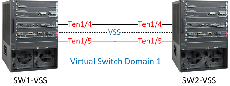
I have two 6500s, one called “SW1-VSS” and the other one is called “SW2-VSS”. I will configure them both to use virtual switch domain 1.
Let’s configure the virtual switch domain ID and switch numbers:
SW1-VSS(config)#switch virtual domain 1
Domain ID 1 config will take effect only
after the exec command 'switch convert mode virtual' is issued

SW1-VSS(config-vs-domain)#switch 1
SW2-VSS(config)#switch virtual domain 1
Domain ID 1 config will take effect only
after the exec command 'switch convert mode virtual' is issued

SW2-VSS(config-vs-domain)#switch 2
Both switches are configured to use virtual domain 1, SW1-VSS has been configured as “switch 1″ and SW2-VSS as “switch 2″. The next step is to assign a priority to determine what switch will become active or standby.
SW1-VSS(config-vs-domain)#switch 1 priority 110
SW1-VSS(config-vs-domain)#switch 2 priority 100
SW2-VSS(config-vs-domain)#switch 1 priority 110
SW2-VSS(config-vs-domain)#switch 2 priority 100
The higher the priority the more likely you will become the active switch. Switch 1 will have a priority of 110 and switch 2 a priority of 100. This means SW1-VSS will become the active switch.
Configure Virtual Switch Link
The virtual switch link is used to exchange configuration and stateful information between the two physical switches. You can use a single physical interface for VSL or create an etherchannel for redundancy. VSL will add a “virtual switch header” on each frame when it is sent on this link, basically it looks like this:
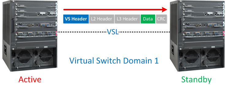
Not all interfaces are supported for VSL. In my example I’m using the Ten Gigabit interfaces on the Supervisors. To make sure we have redundancy I’ll create an etherchannel using the Ten 1/4 and Ten 1/5 interfaces on the 6500s:
SW1-VSS(config)#interface port-channel 1
SW1-VSS(config-if)#no shutdown
SW1-VSS(config-if)#switch virtual link 1
SW1-VSS(config-if)#exit
SW1-VSS(config)#int range ten 1/4 - 5
SW1-VSS(config-if-range)#channel-group 1 mode on
SW1-VSS(config-if-range)#no shut
SW2-VSS(config)#interface port-channel 2
SW2-VSS(config-if)#no shutdown
SW2-VSS(config-if)#switch virtual link 2
SW2-VSS(config-if)#exit
SW2-VSS(config)#int range ten 1/4 - 5
SW2-VSS(config-if-range)#channel-group 2 mode on
SW2-VSS(config-if-range)#no shutdown
As you can see above we have a basic etherchannel configuration but I used the switch vrtual link command to tell the switch that the etherchannel is a VSL interface. Let’s verify that our etherchannel is working between the two switches:
SW1-VSS#show etherchannel summary | incl Po1
1      Po1(RU)          -        Te1/4(P)       Te1/5(P)
SW2-VSS#show etherchannel summary | incl Po2
2      Po2(RU)          -        Te1/4(P)       Te1/5(P)
We are now ready to convert the 6500s to VSS.
Execute Conversion
The final step in configuring VSS is to execute the conversion. Once we do this the switches will reload and 3 things will happen:
- The configurations of both switches will be merged into a single configuration.
- The interface numbers will be renumbered from slot/port to switch-number/slot/port.
- Negotiation to determine which switch is active or standby.
This is how we execute the conversion:
SW1-VSS#switch convert mode virtual

This command will convert all interface names
to naming convention "interface-type switch-number/slot/port",
save the running config to startup-config and
reload the switch.

NOTE: Make sure to configure one or more dual-active detection methods
once the conversion is complete and the switches have come up in VSS mode.

Do you want to proceed? [yes/no]: yes
Converting interface names
Building configuration...
SW2-VSS#switch convert mode virtual

This command will convert all interface names
to naming convention "interface-type switch-number/slot/port",
save the running config to startup-config and
reload the switch.

NOTE: Make sure to configure one or more dual-active detection methods
once the conversion is complete and the switches have come up in VSS mode.

Do you want to proceed? [yes/no]: yes
Converting interface names
Building configuration...
The switches will now reboot and you will see this on the console:
SW1-VSS#
System detected Virtual Switch configuration...
 Interface TenGigabitEthernet 1/1/4 is member of PortChannel 1
 Interface TenGigabitEthernet 1/1/5 is member of PortChannel 1
SW2-VSS#
System detected Virtual Switch configuration...
 Interface TenGigabitEthernet 2/1/4 is member of PortChannel 2
 Interface TenGigabitEthernet 2/1/5 is member of PortChannel 2
And you will see the negotiation between active and standby:
SW1-VSS#
%PFREDUN-6-ACTIVE: Initializing as ACTIVE processor for this switch

%VSL_BRINGUP-6-MODULE_UP: VSL module in slot 1 switch 1 brought up
%VSLP-5-RRP_ROLE_RESOLVED: Role resolved as ACTIVE  by VSLP
%VSL-5-VSL_CNTRL_LINK:  New VSL Control Link  1/1/4
SW2-VSS#
%PFREDUN-6-ACTIVE: Initializing as ACTIVE processor for this switch

%VSL_BRINGUP-6-MODULE_UP: VSL module in slot 1 switch 2 brought up
%VSLP-5-RRP_ROLE_RESOLVED: Role resolved as STANDBY by VSLP
%VSL-5-VSL_CNTRL_LINK:  New VSL Control Link  2/1/4
The two switches rebooted and during the boot process the switches will detect which interfaces are used for the virtual switch link. The switches will then negotiate on the VSL to see which one becomes active or standby. As expected SW1-VSS is the active switch.
After booting you’ll see that the console of SW2-VSS is no longer responding, we can’t use it anymore for configuration. All configurations have to be done from the active switch now.
VSS is now up and running! Since the two switches have bonded to become one logical switch, it’s best to create a new hostname:
SW1-VSS(config)#hostname SW-VSS
I’ll call it “SW-VSS”. We are now done with the configuration but it’s a good idea to verify our configuration.
Verification
The active switch is used to control both switches so some commands have been changed. For example “show run” can now be used to check the running configuration from both switches:
SW-VSS#show run switch 1
Building configuration...

Current configuration : 4283 bytes
!
[output omitted]
SW-VSS#show run switch 2
Building configuration...

Current configuration : 4223 bytes
!
[output omitted]
By adding “switch <id>” you can check the running configuration from switch 1 or 2. There’s also some special VSS commands that we can use:
SW-VSS#show switch virtual
Switch mode                  : Virtual Switch
Virtual switch domain number : 1
Local switch number          : 1
Local switch operational role: Virtual Switch Active
Peer switch number           : 2
Peer switch operational role : Virtual Switch Standby
The show switch virtual command tells us that this switch is active and the other one is standby. We can also take a closer look at the VSL:
SW-VSS#show switch virtual link
VSL Status : UP
VSL Uptime : 28 minutes
VSL SCP Ping : Pass
VSL ICC Ping : Pass
VSL Control Link : Te1/1/4
VSL Encryption : Configured Mode - Off, Operational Mode - Off
This is how you can check the VSL etherchannel:
SW-VSS#show interfaces vsl

VSL Port-channel: Po1
 Port: Te1/1/4
 Port: Te1/1/5
And there’s a useful command that gives you more information about the switch roles and priorities:
SW-VSS#show switch virtual role
RRP information for Instance 1

--------------------------------------------------------------------
Valid  Flags   Peer      Preferred  Reserved
               Count     Peer       Peer

--------------------------------------------------------------------
TRUE    V        1           1          1

Switch  Switch   Status      Priority     Role     Local   Remote
        Number               Oper(Conf)            SID     SID
--------------------------------------------------------------------
LOCAL   1         UP         110(110)     ACTIVE    0       0
REMOTE  2         UP         100(100)     STANDBY   2921    12

Peer 0 represents the local switch

Flags : V - Valid

In dual-active recovery mode: No
[/code]